Perkins Diesel Fuel System Diagram
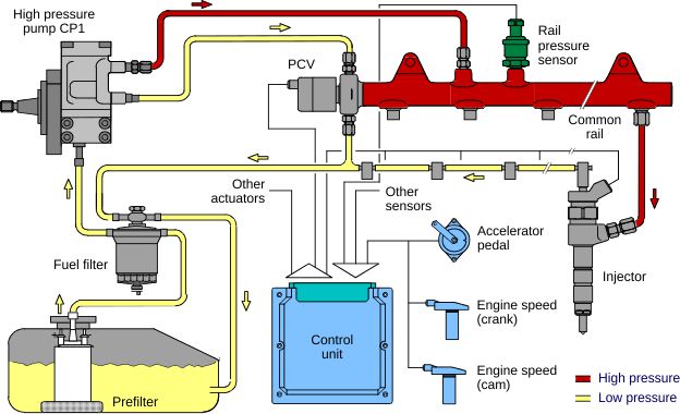
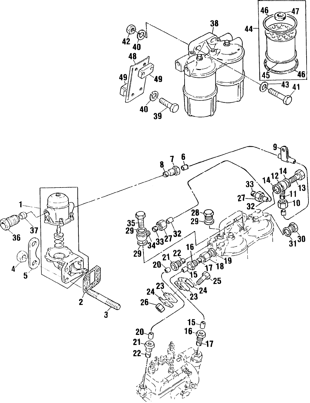
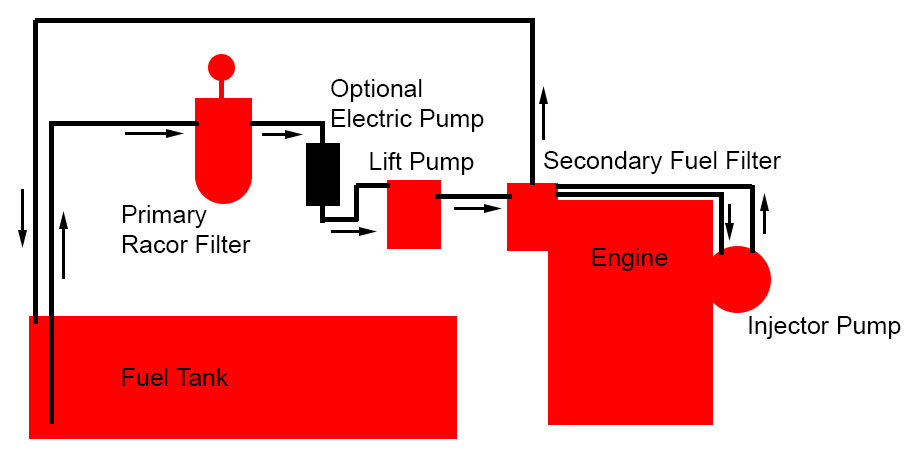
Perkins diesel fuel system diagram. Down from a minimum of 3oto a maximum of 17o. Since we have the electric fuel pump in series with the fuel lift pump it sure seems like running it for a while should clear most of the air out of the system with the possible exception of the last part the high pressure fuel pipes. Stop the engine and.
These engines have been manu-factured with specific options to function integrally with an automatic engine controller for stand-by fire protection ser-. If preservative fuel is not used the system can be kept full with normal fuel but the fuel must be drained and discarded at the end of the storage period together with the fuel filter elements. To Assemble the Combined Bearing and Shaft Type Pump Fig.
Lucas CAV DPS DPC and DP200 hydraulic head O ring seal. For 4 cylinder models. This manual covers Perkins diesel engines as marketed thru Detroit Diesel Corporation.
How to bleed a CAV diesel fuel filter water separatorSubscribe. Requiring only the addition of coolant fuel and battery acid. Perkins Engines Diesel Fuel Line Seal Kit 23 Seals Washers Not Intake Gasket Sets 152 203 212 236 248 Fuel Line Seal Kit 23 Seals Washers Not Intake Gasket Sets Order a Quanitiy of 1 for compl.
Then correct leakage s of fuel lubricating oil or air. If your engine is not a Perkins the exact procedure fittings at the pump. Ive read on some diesel forums that you can also run a diesel of WD-40 into the air intake to lubricate the.
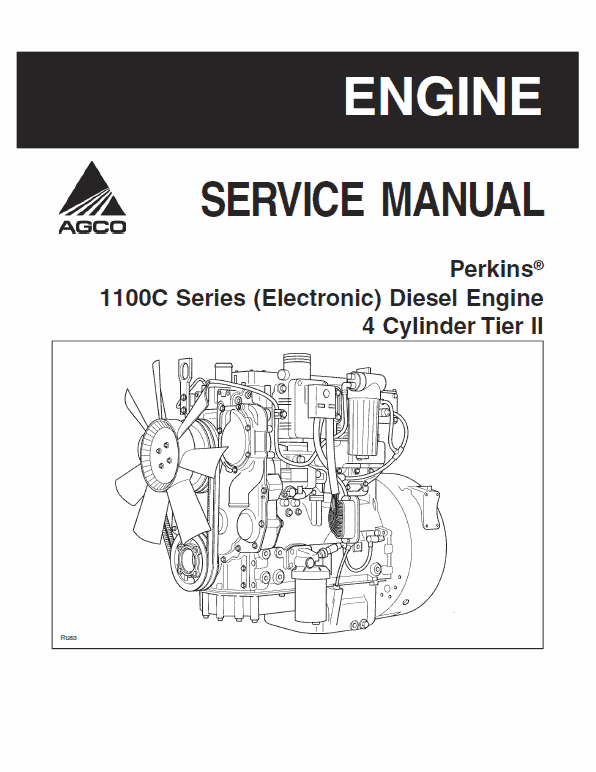
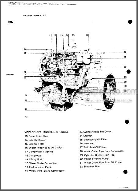
The Perkins 100 Series is a three cylinder four stroke liquid cooled compression ignition engine designed for durability low weight and compactness. 3 Operate the engine until it is warm. Free Download Manual for Perkins 1104D 1106D Engine - Common Rail Fuel System - Pressure Fuel Cooling Fuel Tank Design Technical Data ECM Circuit Diagrams OEM.
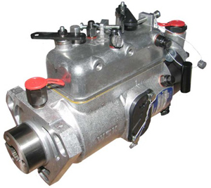
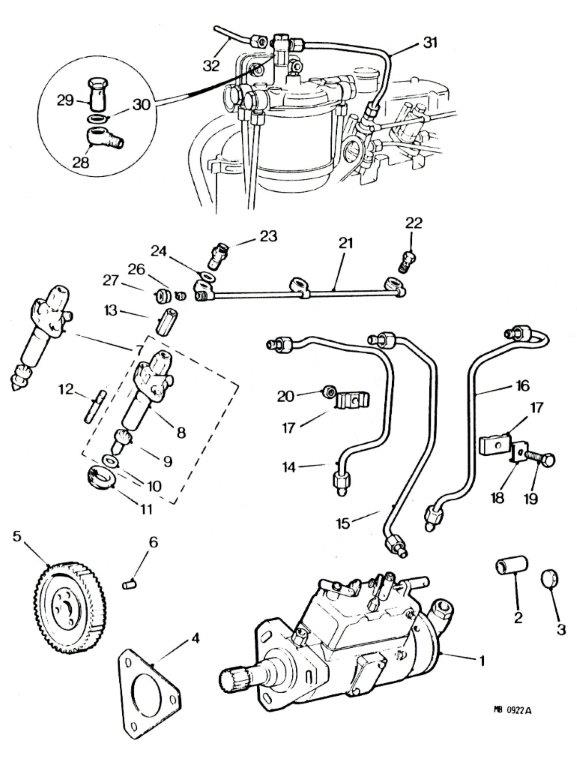
Lucas DPA Distributor-type Injection Pump Automobile Lucas CAV Injection Pump Diagram Lucas Diagram Pumps. CAV BPF-2B Fuel Injection Pump Exploded Parts Diagram.
The diesel driven fire pump system is pre-ferred by most insurance companies.
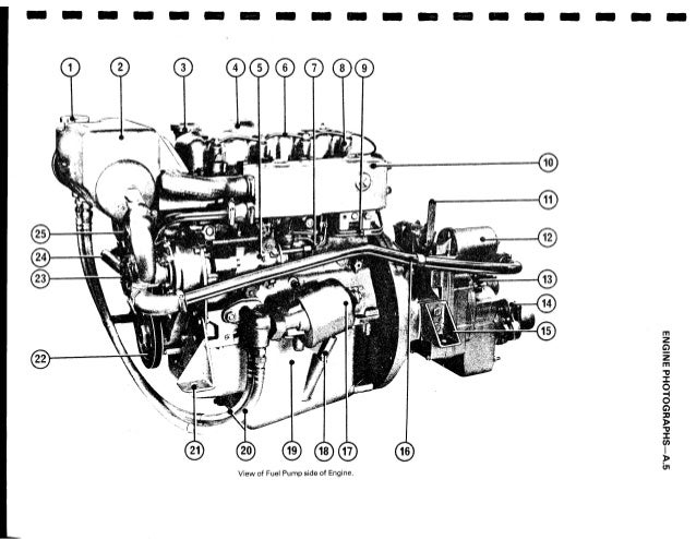
Free Download Manual for Perkins 1104D 1106D Engine - Common Rail Fuel System - Pressure Fuel Cooling Fuel Tank Design Technical Data ECM Circuit Diagrams OEM. This information primarily covers Perkins models 41087 4154 4236 6354 some Westerbeke models that were based on Perkins Engines. For 4 cylinder models. These engines have been manu-factured with specific options to function integrally with an automatic engine controller for stand-by fire protection ser-. CAV BPF-2B Fuel Injection Pump Exploded Parts Diagram. With the pump resting on the front end of the shaft and the pump body unsupported press on the impeller 6 until the rear face of the impeller vanes is 00000006 in 000015 mm below the rear face of the body. The heel angles that are permissible in service are shown in figure 2a for 6 cylinder models and 2b. These models all were fitted with CAV DPA rotary type injector pumps. To Assemble the Combined Bearing and Shaft Type Pump Fig.
Since we have the electric fuel pump in series with the fuel lift pump it sure seems like running it for a while should clear most of the air out of the system with the possible exception of the last part the high pressure fuel pipes. Ive read on some diesel forums that you can also run a diesel of WD-40 into the air intake to lubricate the. The heel angles that are permissible in service are shown in figure 2a for 6 cylinder models and 2b. Requiring only the addition of coolant fuel and battery acid. Lucas DPA Distributor-type Injection Pump Automobile Lucas CAV Injection Pump Diagram Lucas Diagram Pumps. The linerless cylinder block three-piece helical gear train and flange mounted fuel injection pump on the engine. This Technical Operation and Maintenance Manual has been prepared to assist in maintenance and operation of the generator set.












Post a Comment for "Perkins Diesel Fuel System Diagram"